Before starting to implement everything you need a project. If not building and designing from scratch first thing is to reverse-engineer.
So starting my FCB 1010 Arduino powered, I decided to analyze the board and its connections, in order to understand what and how to connect the wires to Arduino.
First of all I tested the IN current from the power cord. The FCB 1010 has 220 Volts to 9 Volts AC/AC current transformer and then the current is rectified to DC with 4 diodes on the main PCB. As my main PCB board does not work, I removed the transformer and the PCB, and use the Arduino Mega and an external AC/DC power supply. I needed to cut the wires to the pedals and corresponding LEDs.

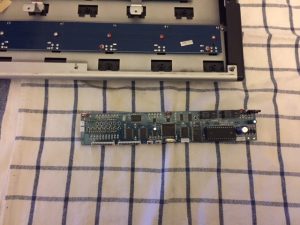
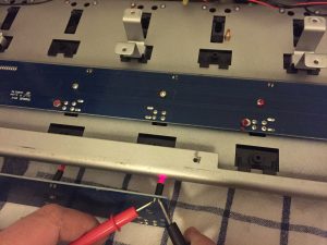
Then I have analyzed all the button pedals and leds circuits: there are two pcb, one with buttons and leds 1,2,3,4,5 and the DOWN button, the second with buttons 6,7,8,9,10 with the correspoding LEDs and the button UP.
The buttons are normal switch buttons you can find in almost every Arduino Starter Kit. They share a “ground wire” and there is a wire per button to close the circuit, so nothing strange.
The LEDs, instead, share a +5 Volts wire and evey LED has a separate ground wire. In my first try I wired the ground wire to the Arduino Digital OUTs. Setting a digital out to HIGH made the LED turn off, while setting it to LOW. Even if this worked (also added a 1 kOhm resistor to not burn up the Arduino), I didn’t like this solution.
I noticed that everything should work well if the LEDs had swapped polarities, so I preferred to desolder the LEDs and solder again with reversed polarity.

Swapping LEDs polarity makes things easier, now very LED has a +5 Volts (from Arduino’s digital ouput) and they all share the same ground wire.